King Point Marina in Plymouth’s Millbay area is located in an dock which was designed by Isambard Kingdom Brunel in 1857 as an associated facility for the Great Western Railway. As constructed the dock entrance was 26m wide and was fitted with mitre lock gates to retain the basin water level. Over time the dock lost its gates and half the basin has been infilled to create marshalling space for Plymouth’s ferry terminal. The remaining portion of the basin has been dredged and converted into a tidal marina with 171 pontoon berths.
While the marina basin is well sheltered from most sectors the wide entrance is open to the south and at high tide southwesterly storm events can result in waves of up to 1.5m significant height entering the marina basin. A means of attenuating these storm waves and protecting the vessels moored in the basin was required by the marina’s owners, Sutton Harbour Holdings plc.
A previous attempt at providing protection with mitre wave gates had failed so marine contractor Land and Water Services (LAWS) engaged Beckett Rankine to find a solution to the problem. The brief, which at first seemed simple, became more challenging as we progressed. The first complicating factor was that Sutton Harbour Holdings did not want the entrance channel narrowed so the option of installing choke structures in the entrance was ruled out. A further constraint was the Environment Agency’s (EA) requirement for the wave height within the basin not to exceed 400mm so as to avoid flooding from wave over-topping during storm surge events.
We investigated hinged or de-mountable chokes but the complications of fixing and then deploying them ruled out that option. Other solutions investigated included bubble screens and water jets which were ruled out on the difficulty of proving their efficacy. A bottom hinged wave gate was a possible solution but the cost of installing and then maintaining it was too high.
Following a rigorous feasibility study the preferred solution was a wave attenuation pontoon that, stored in the marina when not in use, could be deployed across the dock entrance when a storm was forecast. However we first had to prove that a relatively lightweight pontoon could provide sufficient reduction in the wave energy. To establish this the first task was to model the wave climate at the dock entrance. The incident wave condition was established using a SWAN model extending beyond the extent of Plymouth Harbour. The offshore wave spectrum for this model was derived from EA data combined with records from the Looe waverider buoy. The EA were particularly concerned about the future of Plymouth breakwater and the effect of it not being maintained. To assess this case comparative runs were done with the breakwater intact and reduced down to low water level. A return period of 1 in 200 years was used with an allowance for 50 years of sea level rise. See figure 1.
With the wave climate determined at the entrance to Millbay docks we used an ARTEMIS model to examine wave refractions and reflection through the dock entrance and within the basin. A number of runs were carried out using the JONSWAP wave spectra with differing water levels, wave periods and heights. The runs were done with and without an attenuation pontoon in the dock entrance. Example outputs from the modelling are shown in Figures 2 and 3.

This mathematical modelling showed that a wave attenuation pontoon would deliver the desired wave climate within the marina basin providing it had a coefficient of transmission no greater than 0.65. This presents no difficulty for short period waves and long period waves, with a period of 10 seconds or more, have a small amplitude; the problematic waves are of 6-7 second period as they can a significant height of circa 2m. To answer the question of whether a floating attenuator could achieve the necessary performance physical model testing was required. For this we engaged the laboratories at HR Wallingford. HRW modelled the skirted tubular steel pontoon we designed at the scale of 1:16.8; the dock entrance channel was also modelled and installed in the No3 flume which is 100m long, 1.8m wide and can operate with up to 2m water depth. The pontoon was secured on a pair of piles located in the old lock gate recesses.
A total of 17 runs were carried out with a range of water levels and wave heights. The key finding was that provided the pontoon pile guides were designed so as to restrict the pontoon from rolling then a coefficient of transmission of 0.6 could be achieved. The physical model tests also provided an estimation of the loading imposed by the pontoon on its guide piles. See Figure 4 showing a model test run.
Figure 4
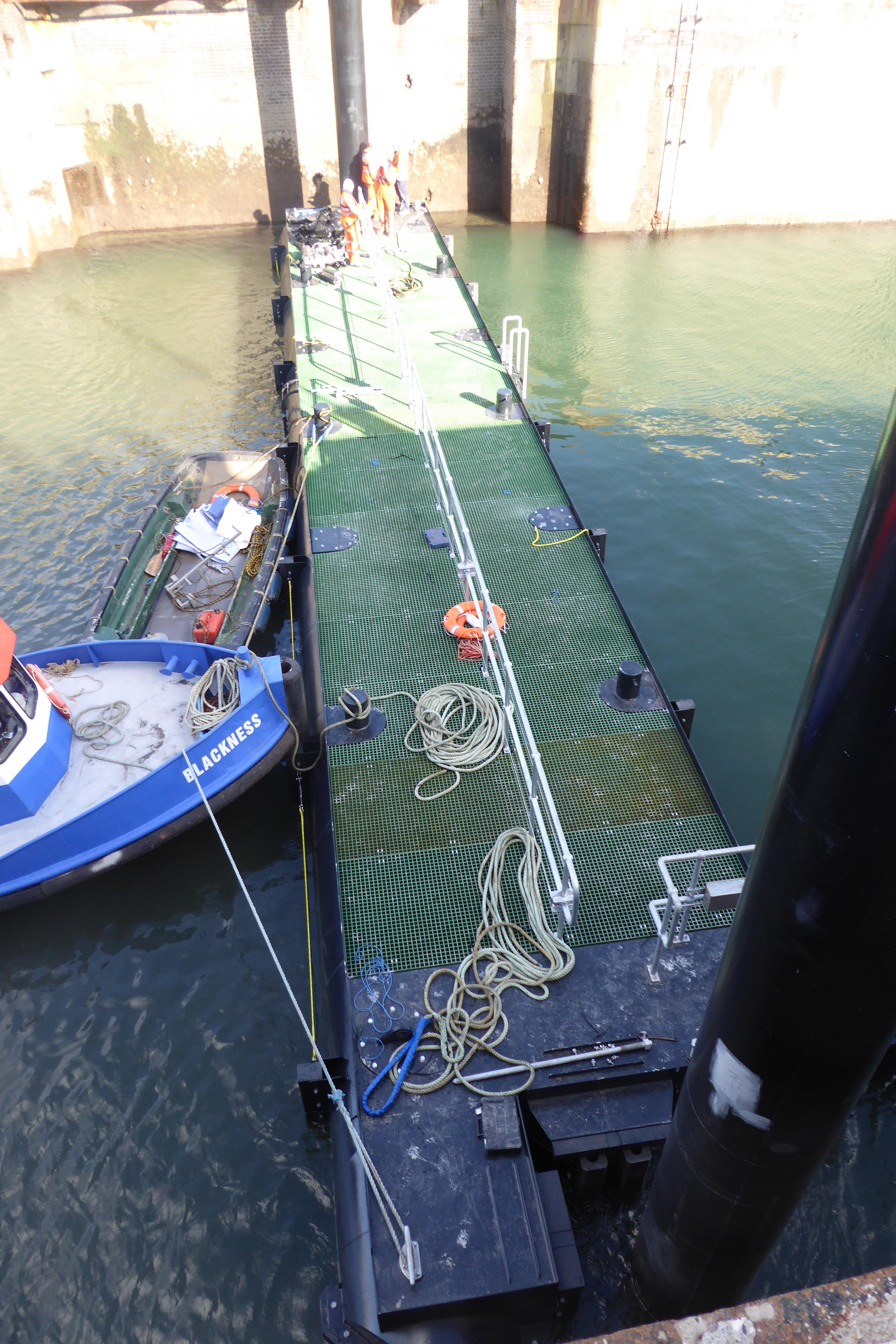
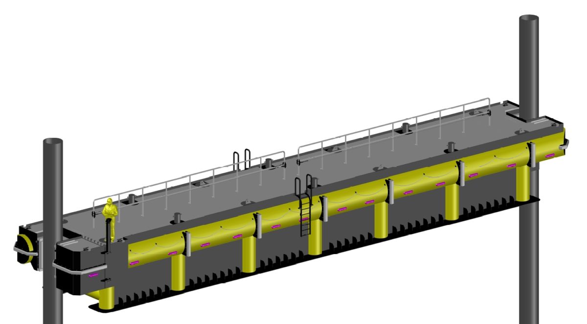
With the concept proved to the satisfaction of the client and EA the task was to develop the detailed design. The design brief required the pontoon to be deployable in no more than 10 minutes by a team of three. To achieve this the critical detail was the movable gate that secures the pontoon to the pile. The design has this hinged and operated by a geared wheel; once the gate is closed a set of securing pins are screwed down to withstand the 100t wave loading that can be imposed on the gate. The two securing piles are rock socketed into the concrete base of the lock and braced back to the lock sides at cope level. We specified abnormally tight tolerances for the piles to avoid any risk of the pontoon binding on them; these tolerances were met by LAWS’ subcontractor Martello Piling.
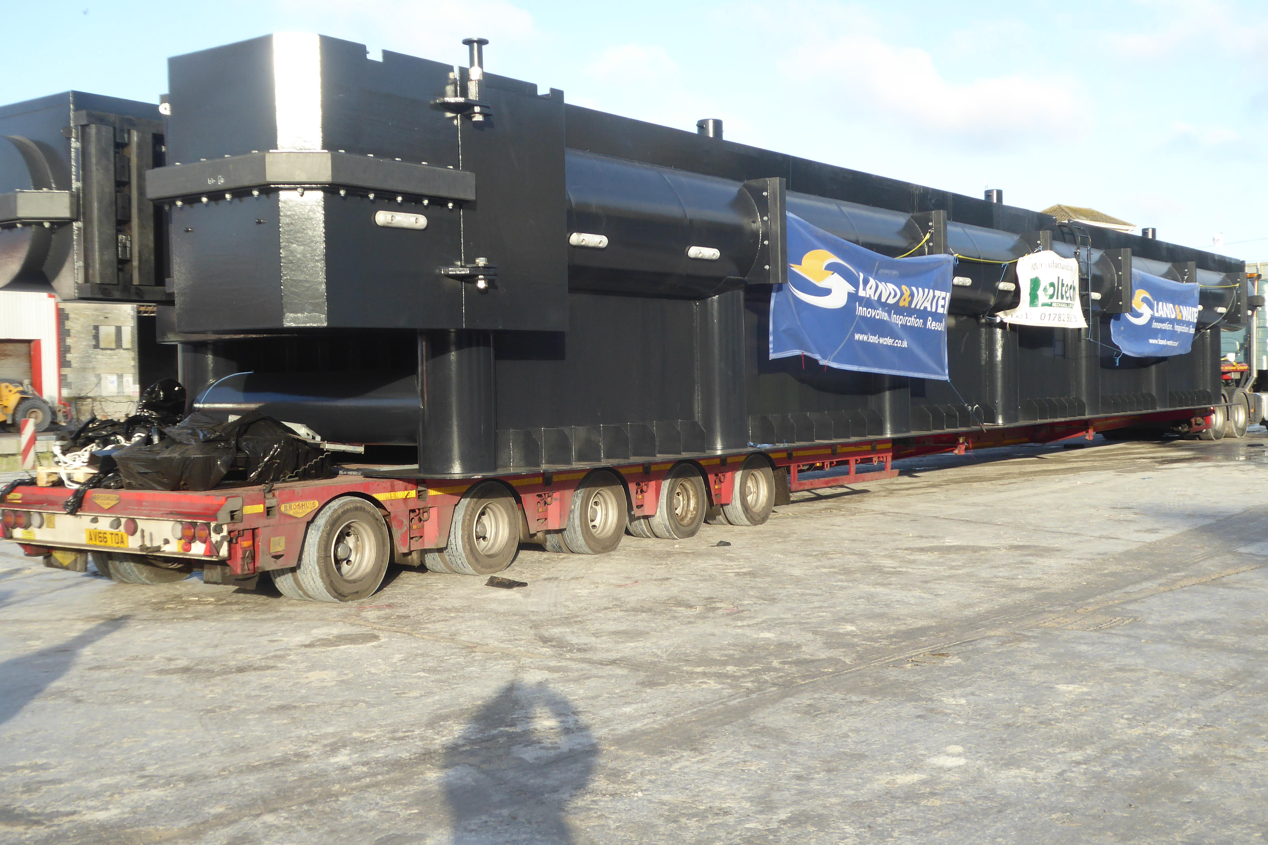
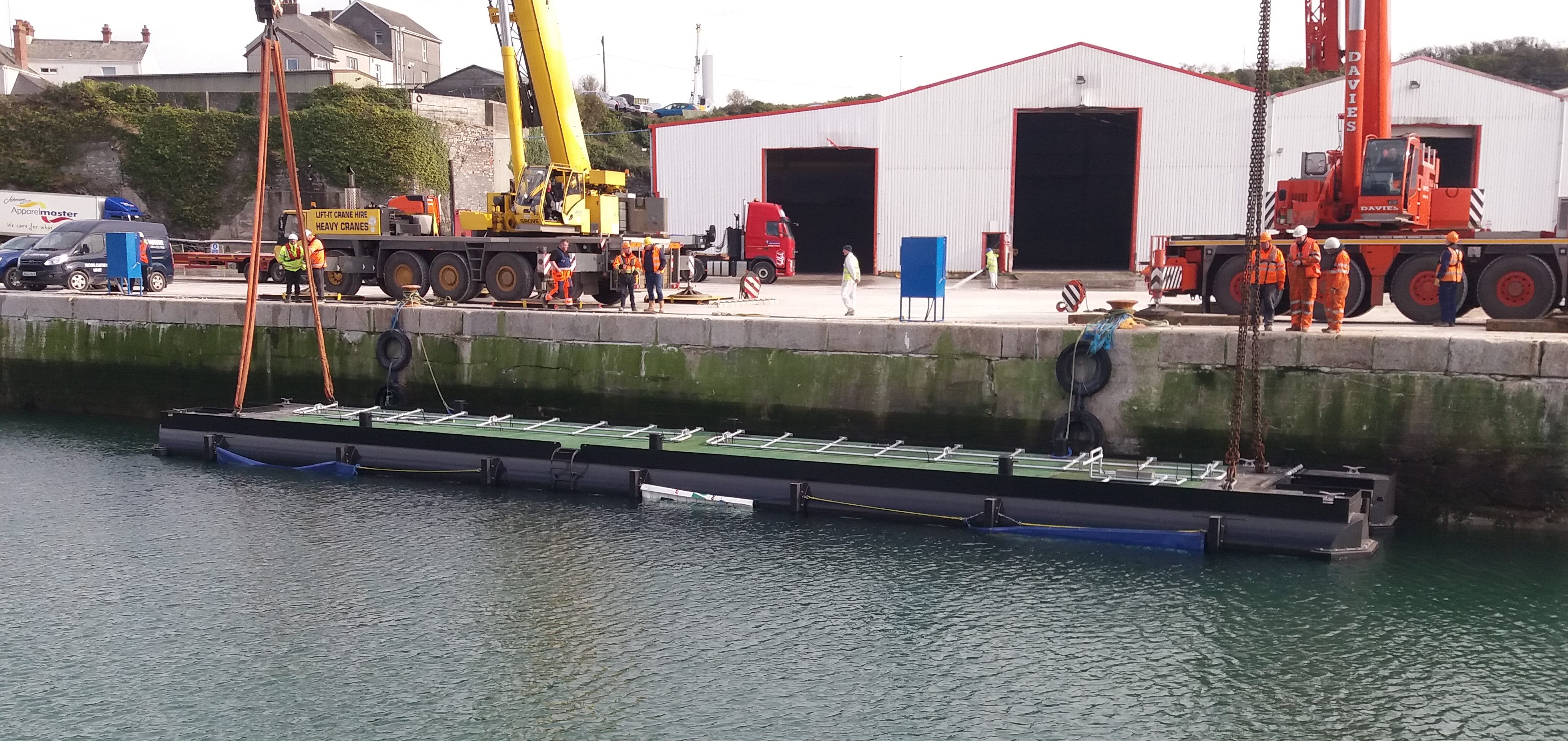
The pontoon measured 25m by 4m with a 2m draft and weighed 56t. It was fabricated by Roltech Engineering in Stoke on Trent and was delivered to Plymouth by road.. Pleasingly it not only floated precisely to its marks when launched but also, the first time it was deployed, it was done in under 10 minutes. King Point Marina can now take comfort from their berths being well protected against storms from any sector.
Our thanks to LAWS for the photos below and the video of the pontoon’s first deployment.